


A wet limestone flue gas desulfurization plant depends on a continuous, stable supply of fine limestone slurry. The grinding plant converts crushed high-calcium limestone into a controlled powder or slurry reagent that can dissolve efficiently in the absorber and react with sulfur dioxide in flue gas.
Although each power plant has its own capacity, limestone source, storage arrangement, and automation requirements, the core process follows the same logic: receive and prepare limestone, grind it to the required fineness, mix it with water, store the slurry under agitation, and feed it to the wet FGD absorber according to operating demand. A typical wet FGD design uses fine limestone near 325 mesh, often with 95% of particles smaller than 44 μm, to improve reagent utilization and limit unreacted limestone in the gypsum product.
Typical Process Route
Limestone receiving → crushing → raw material storage → controlled feeding → fine grinding → powder collection → slurry preparation → slurry storage → metered supply to FGD absorber
When a dry grinding system is used, finished limestone powder is first collected and stored in a powder silo, then mixed with process water in a slurry preparation tank. In some plant layouts, limestone is wet-ground directly with water. The dry-grinding route is often selected where limestone powder must be stored, transported, or supplied to more than one consumption point.
1. Limestone Receiving and Storage
Limestone may arrive at the site by truck, rail, belt conveyor, or ship-to-yard handling system. Before entering the grinding circuit, the material should be inspected for calcium carbonate content, moisture, particle size, clay content, and contamination by metal, wood, or oversized rock.
After unloading, limestone is transferred to a covered stockpile, storage yard, or raw-material silo. Adequate storage capacity is important because FGD operation cannot be interrupted by short-term changes in quarry production, transport conditions, or weather.
For reliable plant operation, the receiving section commonly includes:
Truck or rail unloading station
Receiving hopper with grizzly screen
Apron feeder or vibrating feeder
Belt conveyor system
Magnetic separator for tramp iron removal
Raw limestone stockpile or enclosed storage bin
Dust-suppression or dust-collection equipment
2. Crushing and Feed Size Control
Run-of-quarry limestone is generally too large to enter a fine grinding mill directly. A primary crusher reduces the stone to a manageable size, and a secondary crushing stage may be used when the incoming limestone is especially coarse or variable.
The target feed size depends on the selected mill. In most cases, stable crushed limestone with a controlled maximum size helps maintain steady mill loading and reduces fluctuations in finished-powder fineness. A typical preparation route reduces limestone to less than 25–40 mm before fine grinding, while some wet ball-mill systems use crushed limestone below approximately 25 mm.
Uniform crushing is important because oversized feed can lower production capacity, increase mill vibration, raise power consumption, and create unstable operation in downstream conveying equipment.
3. Controlled Feeding to the Mill
Crushed limestone is transferred from the storage bin to the grinding mill through a regulated feeding system. A weigh feeder, rotary valve, belt feeder, or other metering device maintains a stable feed rate based on the required limestone slurry consumption of the FGD unit.
Mill feed control should be linked with the finished-powder silo level, slurry-tank inventory, absorber operating load, inlet SO2 concentration, and circulating slurry pH. This arrangement prevents sudden shortages or overproduction and allows the grinding plant to respond to changes in boiler load.
A properly designed feeding section usually includes a small buffer bin above the mill. This buffer reduces the effect of upstream conveyor fluctuations and provides a stable material column for continuous grinding.
4. Fine Limestone Grinding
The grinding section determines the final particle size and consistency of the FGD limestone powder. The objective is not merely to produce fine material; it is to produce a stable particle-size distribution that supports fast limestone dissolution without unnecessary energy consumption.
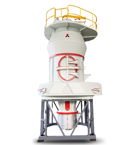
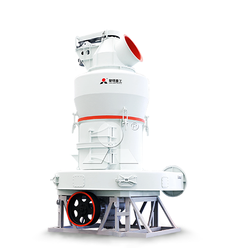
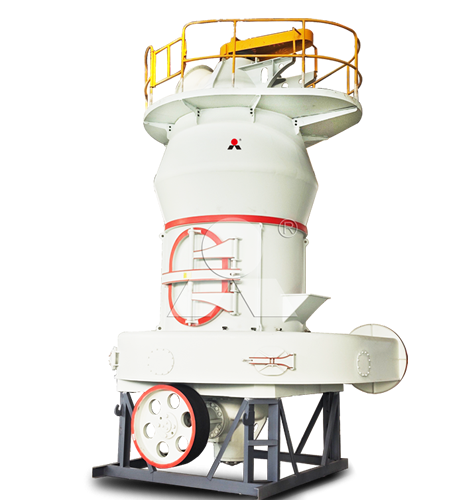
For a dry grinding process, the MTW European Trapezium Grinding Mill from Liming Heavy Industry is suitable for producing fine limestone powder for wet FGD slurry preparation. It can be configured with an integrated classifier to control the finished product and return oversized particles for further grinding. This supports stable production of limestone powder around the commonly required 325-mesh range.
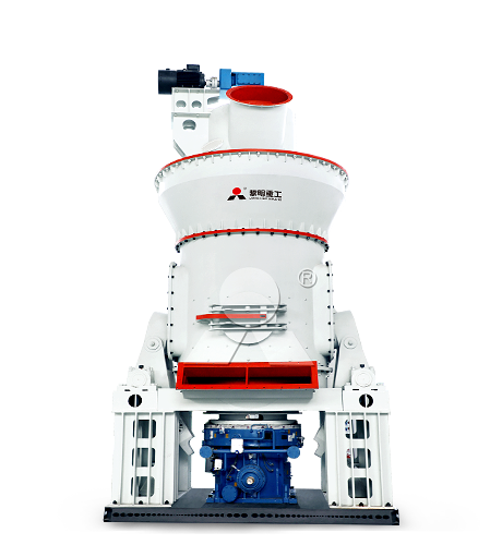
For larger FGD limestone supply systems, the LM Vertical Coal Mill from Liming Heavy Industry can be applied to limestone grinding with a compact process arrangement. Its integrated grinding, classification, drying, and pneumatic conveying functions can reduce the number of separate process units while supporting continuous high-capacity operation.
In both configurations, material that does not meet the target fineness is returned to the grinding zone. Qualified powder is carried with the air stream to the collection system, while coarse particles are separated and reground.
5. Powder Classification and Collection
After grinding, the air-powder mixture enters a classification and collection stage. The classifier separates acceptable fine powder from oversized particles. Fine limestone powder is then captured by a bag filter, pulse dust collector, or another high-efficiency collection device.
Collected powder is discharged through an airlock or rotary valve and conveyed to the finished-product silo. Cleaned air returns to the mill system or is discharged through the dust collector after meeting site emission requirements.
The collection system should be sized for continuous operation because poor dust collection can reduce powder recovery, create unstable mill airflow, increase housekeeping work, and cause material loss.
6. Finished Powder Storage
The finished limestone powder is stored in a sealed silo before slurry preparation. The silo provides a buffer between grinding output and FGD consumption, allowing the mill to operate steadily even when the absorber demand changes over short periods.
A practical limestone powder silo normally includes:
Level indicators for high, low, and emergency inventory control
Bin aeration devices to improve powder discharge
Pressure-relief and vent-filter equipment
Load cells or inventory measurement system
Flow-control valve below the silo outlet
Dust-tight connections for conveying and dosing
Powder storage should remain dry. High humidity can cause limestone powder to cake, bridge, or stick to silo walls, affecting the accuracy of downstream dosing.
7. Slurry Preparation
From the finished-powder silo, limestone is dosed into a slurry preparation tank containing process water. An agitator keeps the solids suspended and ensures that the limestone is distributed uniformly throughout the tank.
The slurry concentration is selected according to absorber design and pumping requirements. A concentrated limestone slurry may be prepared for storage and then diluted before entering the absorber loop. Historical limestone FGD systems have commonly stored slurry at high solids concentration and fed it into the scrubber system as required.
The slurry preparation tank requires sufficient mixing intensity to prevent settlement. It should also have enough retention time for wetting, dispersion, and initial limestone dissolution. If the powder is poorly mixed, local settling can occur, causing blocked pipelines, inaccurate density measurement, and uneven reagent supply.
8. Slurry Storage and Metered Feeding
Prepared slurry is transferred to one or more agitated storage tanks. These tanks provide operational security when the grinding mill is stopped for maintenance, inspection, or short-term raw-material interruptions.
Slurry is pumped from the storage tank to the absorber reaction tank or to a dedicated reagent-feed point. The feed rate is normally adjusted according to circulating slurry pH, flue gas flow, inlet SO2 concentration, and desulfurization target. In a wet FGD system, finely ground limestone is held in an agitated tank and supplied to the absorber as limestone is consumed by the reaction.
Reliable slurry-feed equipment generally includes duty and standby pumps, density measurement, flow measurement, agitator status monitoring, pipeline flushing connections, and automatic control valves.
9. Absorption and Gypsum Formation
Inside the wet FGD absorber, flue gas flows upward while limestone slurry is sprayed downward through multiple nozzles. The counter-current contact between gas and slurry promotes SO2 absorption. The treated gas passes through a mist eliminator before leaving the tower, while the slurry collects in the absorber sump or reaction tank.
In a limestone forced-oxidation system, air is introduced into the reaction tank to convert sulfite compounds into gypsum. This oxidation stage supports the formation of calcium sulfate dihydrate, commonly known as gypsum.
The simplified overall reaction is:
CaCO3 + SO2 + ½O2 + 2H2O → CaSO4·2H2O + CO2
A portion of the slurry is continuously recirculated to the absorber. Another portion is withdrawn as bleed slurry for gypsum dewatering. The withdrawn slurry is commonly processed through hydrocyclones, filters, or filter presses, while recovered water is returned to the system.
Key Control Points
Stable FGD performance depends on the coordination of grinding, slurry preparation, and absorber operation. The following parameters should be monitored continuously or at regular intervals:
Limestone CaCO3 content and impurity level
Crushed limestone feed size and moisture
Mill feed rate, differential pressure, vibration, and power consumption
Finished limestone powder fineness and particle-size distribution
Powder silo inventory and discharge condition
Slurry density, solids concentration, and tank agitation status
Absorber slurry pH and oxidation-reaction conditions
Inlet SO2 concentration and flue gas flow rate
Gypsum quality, moisture, and residual unreacted limestone content
Process Design Principle
A wet FGD limestone grinding plant should be designed as a connected reagent-supply system rather than as an isolated milling unit. Crushing capacity, grinding capacity, powder storage, slurry tank volume, pump redundancy, and control logic must be matched to the maximum sulfur load of the boiler.
When limestone quality is stable, finished powder is consistently fine, and slurry preparation remains reliable, the absorber can maintain efficient SO2 removal with lower risk of scaling, settling, reagent waste, and gypsum-quality fluctuation. The essential wet limestone FGD sequence—reagent processing, gas absorption, solids formation, and solids dewatering—is well established in power-plant desulfurization practice.
Related FGD Limestone Grinding Plant


Liming Heavy Industry at bauma CONEXPO INDIA 2026 | Booth 5-C6
2026-09-07

Turnkey Raw Mill Cement Plant in Saudi Arabia: Design and Installation
2026-09-03
Cement Raw Mill Supplier in Indonesia: Cost and Configuration Analysis
2026-09-01
Liming Heavy Industry to Exhibit at the 24th Global Gypsum Conference & Exhibition in Turkey
2026-08-31
Complete Calcium Carbonate Grinding and Coating Plant Solution
2026-08-29
Complete Mineral Processing Solutions
Convenient Reliable Professional Efficient Get Your Quote
Please feel free to submit your inquiry information to us. We will contact with you as soon as possible.
Our team will contact you as soon as possible.