


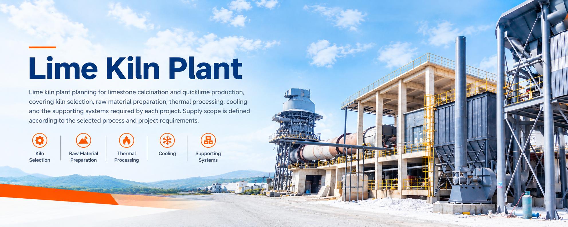
A lime kiln plant layout should follow the movement of limestone, fuel, process gases, and finished quicklime while providing safe access for operation and maintenance. The main systems include raw-material receiving and preparation, kiln feeding, calcination, cooling, exhaust treatment, product handling, storage, and dispatch. Electrical distribution, utilities, control facilities, and maintenance infrastructure must be planned alongside the production equipment.
The objective is not simply to fit a kiln onto the available land. A workable layout must allow the complete plant to operate, be maintained, and accommodate the intended production schedule without creating unnecessary material transfers or access restrictions.
Start with a Process Flow, Not an Equipment Drawing
Before locating individual machines, establish what the plant receives and what it must deliver. A project producing lump quicklime has a different downstream arrangement from one supplying both lump lime and ground quicklime powder.
The initial design basis should define:
The limestone source, analysis, delivery method, and available size distribution.
The required quicklime output and product-quality specification.
The proposed fuel and its storage or supply requirements.
The finished-product forms and expected split between them.
The operating schedule and required storage buffers.
Site boundaries, terrain, access roads, utilities, and expansion plans.
Early lime-project studies commonly combine process flow diagrams, kiln-capacity selection, preliminary layouts, and capital-cost estimates. Developing these together makes the layout a basis for project decisions rather than an illustration prepared after equipment selection.
Organize the Plant into Connected Operating Areas
Raw-Material Receiving and Preparation
Locate limestone receiving so that incoming vehicles can unload without blocking finished-product dispatch or maintenance traffic. Allow space for the required stockpiles, preparation equipment, rejected fractions, and access for cleaning and inspection.
The preparation area should provide a clear route for acceptable kiln feed and a separate destination for oversize and undersize material. Stockpiling, reclaiming, and material-handling systems are substantial parts of lime-plant design, not minor connections between larger machines.
Kiln Feed Storage and Charging
Place the feed buffer and charging system according to the selected kiln’s inlet position and operating requirements. Confirm the transfer height, weighing arrangement, screening requirements, and maintenance access before fixing structural elevations.
The buffer capacity should reflect the operating relationship between limestone preparation and the kiln. If these sections work different schedules, the storage requirement must be calculated accordingly rather than chosen from a standard bin size.
Calcination and Cooling
The kiln and cooling arrangement establish many of the plant’s principal elevations and equipment interfaces. In a rotary system with a preheater and cooler, the relative positions support material transfer, gas movement, and heat recovery.
For a Liming Heavy Industry lime kiln project, obtain the proposed equipment arrangement and maintenance requirements before committing to the main foundations. Check the space needed for access around charging equipment, drives, firing systems, discharge equipment, and cooling components.
Exhaust Treatment and Draft Equipment
Reserve space for the proposed gas-treatment equipment, fans, ducts, stack, and collected-dust handling. Treat these as process-connected systems rather than equipment that can be placed wherever land remains.
The layout should also provide access for filter maintenance, fan servicing, instrument inspection, and residue removal. Lime-plant engineering includes these process connections and equipment-access requirements within the broader facility design.
Finished-Product Storage and Dispatch
Position product storage around the required delivery method. Bulk truck loading, bagging, and feed to a grinding section need different arrangements.
Keep product grades identifiable and provide enough access for inspection and maintenance around discharge equipment. Lime-handling systems must be selected for the material characteristics, site conditions, and customer requirements rather than storage capacity alone.
How Kiln Type Changes the Layout
| Kiln Option | Layout Emphasis | Questions to Resolve Early |
|---|---|---|
| Vertical shaft lime kiln | Vertical material movement, elevated charging, and lower-level discharge. | How will limestone reach the charging point, and how will elevated equipment be inspected and maintained? |
| Rotary lime kiln | The longitudinal equipment arrangement and interfaces with the preheater, cooler, and firing system. | Where are the required service areas, equipment-removal routes, and duct connections? |
| Twin-shaft lime kiln | The connected shaft arrangement, charging equipment, operating valves, and discharge systems. | How will both shafts and shared components remain accessible throughout operation and maintenance? |
For Liming Heavy Industry vertical shaft, rotary, or twin-shaft lime kiln proposals, compare the complete installed arrangement. The kiln’s equipment footprint alone does not establish the land requirement for the production plant.
Maintenance Space Is Part of the Production Footprint
A machine may fit physically while remaining difficult to service. Before approving the general arrangement, review the maintenance tasks that determine clearance and access.
Removal and replacement of drives, motors, fans, and major valves.
Access to charging and discharge components.
Refractory-work staging and material movement.
Inspection and servicing of elevated equipment.
Lifting positions and routes for replacement parts.
Access to electrical equipment and local control stations.
Equipment foundations, structural supports, access platforms, and maintenance infrastructure belong in the multidisciplinary design scope. Leaving them until late in the project can force changes to equipment positions and connections.
Separate Vehicle Movement from Routine Operating Access
Map the expected movements of limestone deliveries, fuel deliveries, product trucks, mobile equipment, and maintenance vehicles. Check unloading and loading positions against actual vehicle dimensions and site access constraints.
Where practical, avoid routes that require delivery vehicles to reverse through busy operating areas or queue across maintenance access. Include pedestrian routes, emergency access, and the space needed for inspections and sampling.
Storage and dispatch planning should also account for the customer’s transport arrangement. A production line can operate steadily while dispatch remains intermittent, making the loading schedule and available storage important parts of the layout brief.
Resolve Utilities and Civil Conditions Before Freezing the Plan
Electrical and Control Facilities
Identify the incoming power connection, distribution equipment, motor-control facilities, cable routes, and control-room requirements. Coordinate these locations with maintenance access and the equipment’s environmental conditions.
Fuel Infrastructure
The selected fuel determines whether the plant needs a gas-supply station, liquid-fuel facilities, or solid-fuel receiving and preparation. If a Liming Heavy Industry grinding mill is being evaluated for a combustible-fuel duty, include the required safety assessment and equipment provisions in that scope rather than treating it as an ordinary mineral-grinding installation.
Ground Conditions and Drainage
Confirm the survey, geotechnical information, foundation requirements, and drainage concept before finalizing heavy-equipment locations. Civil and structural engineering are integral to lime-production installations and expansions.
Drainage planning should keep water away from quicklime handling and storage. Coordinate roofs, surface falls, and utility routes so that the site’s water-management system does not create an unintended moisture path into the product.
Plan Grinding as a Defined Product Route
If quicklime powder is required, locate the grinding section according to its feed source, cooled-product conditions, collection system, and finished-powder destination.
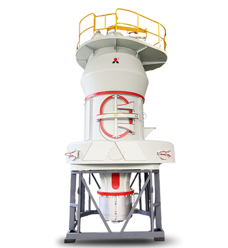
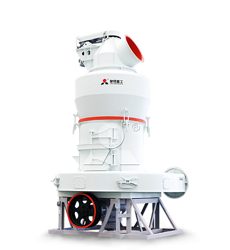
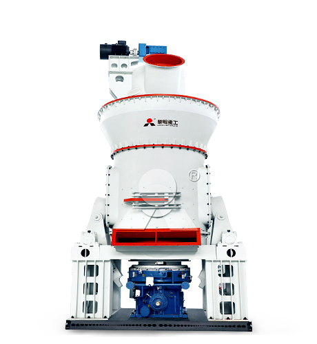
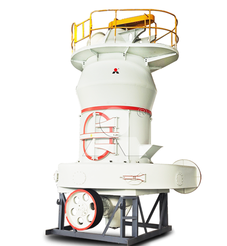
A Liming Heavy Industry grinding mill can be evaluated against the required feed size, temperature, fineness, and throughput. Include its buffer storage, feeding equipment, process-air collection, maintenance area, and powder-storage connections in the layout.
Where the plant sells both lump and ground quicklime, define the routing and capacity split. This avoids sending all production through a grinding area that only needs to handle part of the output.
Make Expansion Physically Possible
Future expansion requires more than an empty plot beside the kiln. Identify how another production line would connect to receiving, utilities, storage, exhaust management, and dispatch.
Reserve the necessary access and connection corridors, and identify any shared system that may become a capacity constraint. Also consider how construction could proceed without unnecessarily disrupting the operating line.
The value of expansion space depends on its accessibility: land that cannot be reached by construction equipment or connected to the process may offer little practical flexibility.
Use Three Reviews Before Approving the Layout
Process review: verify material routes, storage duties, equipment capacities, gas connections, and operating interfaces.
Operations and maintenance review: check access, lifting, equipment removal, sampling, cleaning, and interruption procedures.
Site and execution review: confirm civil conditions, utilities, vehicle movements, construction access, and the boundaries of each supplier’s responsibility.
The resulting arrangement should show more than equipment outlines. It should identify principal elevations, maintenance envelopes, roads, structures, utility areas, and reserved expansion zones.
A practical lime kiln plant layout connects production requirements with the realities of the site. Establishing those relationships early provides a stronger basis for equipment selection, investment planning, construction, and reliable operation than arranging individual machines after purchase.
Related Lime Kiln Plant


LIMING Heavy Industry to Participate in SIREXE 2026 in Abidjan, Côte d'Ivoire
2026-10-26

LIMING at MiningMetals Uzbekistan 2026 | Booth B94
2026-10-22
LIMING Heavy Industry at MINEXPO Africa 2026 | Booth 133
2026-10-22
Liming Heavy Industry to Exhibit at bauma CHINA 2026 – Visit Us at Booth E6.510
2026-10-15
Meet Liming Heavy Industry at the 140th Canton Fair 2026
2026-10-13
Complete Mineral Processing Solutions
Convenient Reliable Professional Efficient Get Your Quote
Please feel free to submit your inquiry information to us. We will contact with you as soon as possible.
Our team will contact you as soon as possible.