


A new FGD limestone grinding project should be planned from the absorber’s maximum reagent demand, the actual limestone source, and the required operating availability. The mill selection comes after these process inputs are defined—not before—because capacity, fineness, storage, slurry preparation, and redundancy must all match the maximum sulfur dioxide removal duty.
Modern wet limestone FGD systems are commonly designed for high SO2 removal, with advanced systems capable of more than 95% removal. Their limestone preparation systems must deliver consistent, reactive powder, commonly near 95% passing 325 mesh, while maintaining enough inventory to protect the absorber during grinding interruptions.
1. Define the Design Basis
The design basis is the technical foundation of the entire project. It should use the worst credible operating condition rather than annual average values. If the plant may burn several coal types, use the highest expected sulfur case or develop separate design cases for each fuel range.
| Design Input | Required Information | Why It Matters |
|---|---|---|
| Boiler operating load | Minimum, normal, maximum, and future uprated capacity | Defines flue-gas volume and maximum FGD reagent demand. |
| Coal consumption | t/h at each operating load and fuel condition | Used to calculate sulfur entering the boiler and potential SO2 generation. |
| Coal sulfur content | Typical, maximum guaranteed, and expected future sulfur range | Higher sulfur content directly increases limestone consumption and gypsum production. |
| Flue-gas conditions | Maximum and minimum gas flow, inlet SO2, temperature, oxygen, dust loading, and humidity | Determines absorber duty and helps establish the maximum SO2 removal load. |
| Required SO2 removal | Emission target, design removal percentage, and operating margin | Determines how much SO2 must be neutralized by limestone slurry. |
| Limestone source | Quarry location, supply capacity, CaCO3, MgO, SiO2, moisture, hardness, and reactivity | Controls required reagent quantity, grinding energy, wear rate, and finished powder specification. |
| Target powder fineness | Control-sieve residue and particle-size distribution required by the FGD process supplier | Determines mill capacity, classifier configuration, energy consumption, and powder handling conditions. |
| Availability requirement | Required annual availability, maintenance philosophy, and allowable mill outage time | Determines the need for parallel mills, standby equipment, and powder-storage capacity. |
| Site constraints | Available area, building height, foundation conditions, power supply, water supply, road access, and climate | Influences plant layout, conveying method, drying requirement, installation sequence, and construction cost. |
The FGD system should be designed around maximum and minimum gas flow, SO2 concentration, flue-gas temperature, dust loading, limestone quality, emission requirement, and critical-equipment redundancy.
2. Calculate Limestone Demand
The required grinding capacity starts with the amount of SO2 to be removed at maximum duty. The basic wet limestone reaction is:
CaCO3 + SO2 + ½O2 + 2H2O → CaSO4·2H2O + CO2
One tonne of sulfur creates approximately two tonnes of SO2. One tonne of SO2 removed theoretically requires 1.5625 tonnes of pure CaCO3. Actual consumption must then be corrected for limestone purity and the operating Ca/S molar ratio.
SO2 generation (t/h) = Coal consumption (t/h) × sulfur content × 2
Removed SO2 load (t/h) = SO2 generation × required removal efficiency
Required limestone powder (t/h) = Removed SO2 load × 1.5625 × Ca/S ratio ÷ CaCO3 purity
For preliminary planning, a Ca/S molar ratio around 1.03 and limestone containing 90% CaCO3 can be used as initial assumptions. Final values should be confirmed through FGD process design and limestone reactivity testing.
For example, consider a project with 250 t/h coal consumption, 1.0% sulfur, 98% SO2 removal, a Ca/S ratio of 1.03, and 90% CaCO3 limestone:
Sulfur load = 250 × 0.01 = 2.50 t/h sulfur
SO2 generated = 2.50 × 2 = 5.00 t/h SO2
SO2 removed = 5.00 × 0.98 = 4.90 t/h SO2
Required limestone powder = 4.90 × 1.5625 × 1.03 ÷ 0.90 = 8.76 t/h
The grinding plant should not be selected at exactly 8.76 t/h. It needs margin for changing limestone quality, equipment wear, maintenance periods, and short-term high sulfur conditions.
3. Select the Process Route
The main process route should be selected after reviewing limestone moisture, feed size, required fineness, water availability, site layout, and the plant’s maintenance strategy.
| Process Route | Typical Flow | Best-Fit Conditions |
|---|---|---|
| Dry grinding and slurry preparation | Crushing → dry grinding → classification → powder collection → silo storage → mixing with water → slurry storage → absorber | Projects requiring powder inventory, flexible mill operation, controlled dry powder transport, or supply to multiple slurry tanks and FGD units. |
| Wet grinding and direct slurry preparation | Crushing → wet grinding with water → classification → slurry storage → absorber | Projects with suitable water availability, limited need for dry powder storage, and a process arrangement built around direct slurry production. |
For a dry grinding route, the process should normally include raw limestone crushing, controlled feed storage, fine grinding, classification, dust collection, finished-powder storage, accurate powder dosing, slurry preparation, slurry storage, and duty-and-standby pumps.
Dry grinding provides a useful operating buffer because powder can be stored in a silo before slurry preparation. This allows the grinding mill to operate independently from short-term changes in absorber demand and gives the plant more flexibility during maintenance.
4. Select the Grinding Mill
The selected mill must meet the guaranteed output at the specified FGD fineness using the actual limestone source. The mill should not be selected from a nominal capacity range alone. Feed moisture, Bond Work Index, hardness, silica content, feed size, target particle-size distribution, and operating hours can significantly change the achievable capacity.
| Project Condition | Recommended Equipment | Selection Rationale |
|---|---|---|
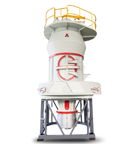
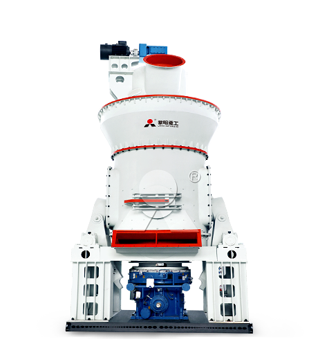
| Large-scale central limestone preparation plant, multi-unit power station, high continuous reagent consumption, or need for integrated drying and conveying | LM Vertical Mill from Liming Heavy Industry | Suitable for large FGD limestone powder projects requiring integrated grinding, classification, drying, and pneumatic conveying in a compact process arrangement. |
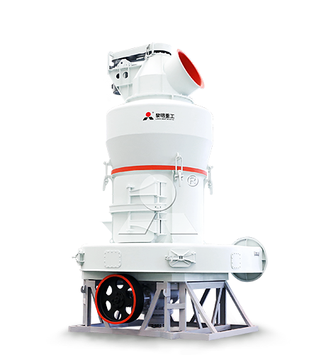
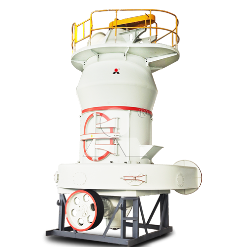
| Medium-capacity FGD powder line, industrial boiler project, retrofit installation, or localized limestone slurry preparation station | MTW European Mill from Liming Heavy Industry | Suitable for medium FGD powder production requiring controlled fine grinding, adjustable classification, and practical connection to powder storage and slurry preparation equipment. |
The capacity calculation should include an availability correction:
Required mill capacity = Maximum limestone consumption × production margin ÷ expected mill availability
For example, if maximum consumption is 8.76 t/h, the project requires a 10% production margin, and expected mill availability is 90%:
Required mill capacity = 8.76 × 1.10 ÷ 0.90 = 10.71 t/h
The selected mill should therefore guarantee at least about 11 t/h of qualified limestone powder at the required FGD fineness under actual feed conditions.
5. Plan Storage and Redundancy
Grinding capacity alone cannot protect FGD availability. The project needs a deliberate reserve strategy covering raw limestone, finished powder, slurry inventory, pumps, critical feeders, and major maintenance periods.
| System Area | Planning Requirement | Typical Reliability Measure |
|---|---|---|
| Raw limestone storage | Maintain sufficient inventory for transport, quarry, or weather disruptions. | Covered stockpile, storage shed, or enclosed raw-material silo with reliable reclaiming equipment. |
| Crushing and feed storage | Provide enough crushed-limestone buffer to maintain steady mill feed. | Intermediate bin, controlled feeder, metal removal, and bypass or maintenance access where appropriate. |
| Grinding system | Maintain production through planned maintenance and high-demand periods. | One large mill with adequate powder reserve, two parallel mills, or one duty and one standby line depending on required availability. |
| Finished powder storage | Supply slurry preparation while the mill is temporarily unavailable. | Silo sized for the required number of hours of maximum limestone consumption. |
| Slurry preparation | Prevent interruptions caused by feeder, mixer, or instrument problems. | Agitated preparation and storage tanks, accurate dosing, density measurement, and water-flow control. |
| Slurry delivery | Maintain feed to the absorber without a single-pump failure becoming a system outage. | Duty-and-standby slurry pumps, isolation valves, flow measurement, and flushing-water connections. |
| Dust collection | Maintain stable airflow and powder recovery. | Correctly sized pulse bag filter, hopper-level monitoring, compressed-air backup, and differential-pressure control. |
For reference, a wet FGD system upgrade study notes that increasing SO2 removal can require higher limestone consumption, finer grinding, and a review of reagent preparation and dewatering capacity. The absorber, reagent preparation, and solids-handling systems should therefore be planned as one connected process rather than as separate packages.
Finished-powder silo capacity can be estimated using:
Usable powder storage (t) = Maximum limestone consumption (t/h) × required backup time (h)
For a plant consuming 11 t/h of limestone powder, a 24-hour operating reserve requires at least 264 t of usable powder inventory. The physical silo must be larger because it also needs allowance for dead stock, freeboard, and bulk-density variation.
6. Complete the Engineering Package
Once the design basis, material balance, process route, mill selection, and reserve strategy are defined, prepare a complete engineering package before procurement. This avoids mismatches such as a correctly sized mill feeding an undersized silo, powder conveyor, slurry tank, or pump.
The package should include:
Design basis document covering boiler load, fuel range, SO2 duty, limestone quality, required fineness, and availability target.
Representative limestone test report covering CaCO3, MgO, SiO2, moisture, hardness, abrasiveness, bulk density, and reactivity.
FGD limestone consumption calculation for normal, maximum, and future operating cases.
Process flow diagram showing crushing, grinding, classification, collection, storage, slurry preparation, and absorber feed.
Material balance and slurry balance for each operating case.
Equipment list with capacity, duty, standby requirement, materials of construction, and power demand.
General arrangement drawing with access routes, maintenance space, lifting points, and truck or rail unloading arrangements.
Electrical load list, motor-control philosophy, variable-frequency-drive scope, and emergency power requirements.
Control narrative covering mill feed, classifier control, powder-silo level, slurry density, tank level, and absorber-demand response.
Dust collection, ventilation, drainage, fire protection, noise control, and safety-access design.
Commissioning plan with performance-test requirements for capacity, fineness, energy consumption, and slurry quality.
Critical-spare-parts list and preventive-maintenance plan for grinding parts, classifier components, filters, fans, feeders, and pumps.
A new FGD limestone grinding project succeeds when the whole reagent-preparation chain is sized from real plant conditions: limestone quality, peak SO2 load, required fineness, operating reserve, and maintenance philosophy. For large, centralized supply systems, the LM Vertical Mill provides the appropriate integrated grinding route. For medium-capacity projects, the MTW European Mill offers a practical fine-powder solution. In both cases, the mill, storage system, slurry preparation tanks, conveying equipment, and pumps should be engineered as one continuous system.
Related FGD Limestone Grinding Plant


Liming Heavy Industry at bauma CONEXPO INDIA 2026 | Booth 5-C6
2026-09-07

Turnkey Raw Mill Cement Plant in Saudi Arabia: Design and Installation
2026-09-03
Cement Raw Mill Supplier in Indonesia: Cost and Configuration Analysis
2026-09-01
Liming Heavy Industry to Exhibit at the 24th Global Gypsum Conference & Exhibition in Turkey
2026-08-31
Complete Calcium Carbonate Grinding and Coating Plant Solution
2026-08-29
Complete Mineral Processing Solutions
Convenient Reliable Professional Efficient Get Your Quote
Please feel free to submit your inquiry information to us. We will contact with you as soon as possible.
Our team will contact you as soon as possible.